Analyzing Inter-Wellbore Fracture Communication
AccuMap Wellbore 3D Viewer provides a highly automated workflow related to gathering data for inter-wellbore fracture communication analysis. AccuMap Wellbore 3D Viewer scans the nearby area for identified offset wells (IOWs) and then creates a report stub and summary.
To analyze inter-wellbore fracture communication
- With the subject well displayed on the map, ensure a directional survey (either actual or proposed) is attached to the subject well. Alternatively, you can use a well that does not have a directional survey attached to identify at-risk offset wells, however, parameters such as the Downhole Lateral Proximity to Subject Well option will be less accurate.
Using the Profile Viewer: Completions tab, you can also add to the subject well proposed Multi-Stages Fracs or add just the Single Frac Range from the top-most stage to the deepest stage.
- Launch Wellbore 3D Viewer for the subject well and set the Well Search Radius and the Offset NE-SW options to their maximum values.
The dialog box appears.
- Using the Structural Surfaces pane, select the nearest horizon below the target formation, which will serve as a canvas for rendering the buffer zone and the IOW.
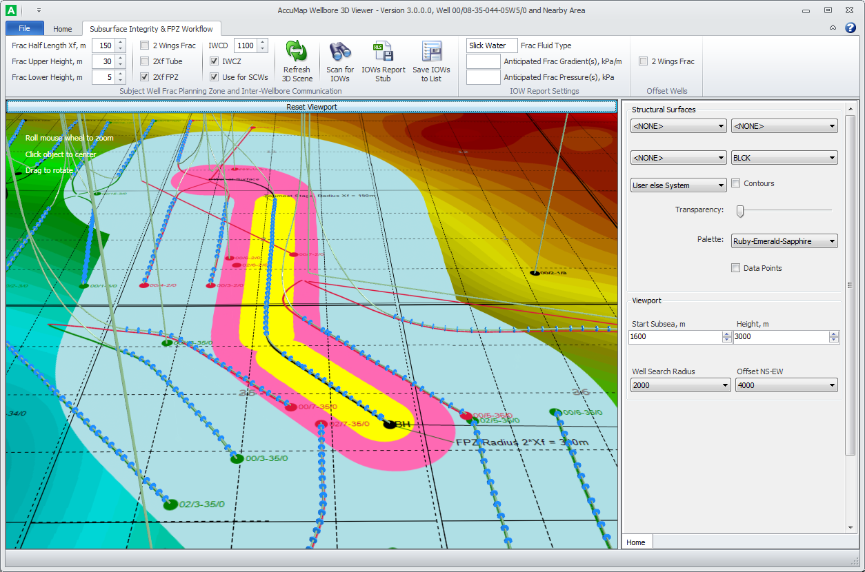
- Using the Subsurface Integrity & FPZ Workflow tab, select the 2Xf FPZ check box.
Wellbore 3D Viewer uses the following colors to identify objects rendered on the structural canvas:
- Yellow - the Frac Half Length XF zone (if system or user fracs for the subject well are detected). Frac Half Length Xf is the radial distance initiated from the subject wellbore to the outer tip of a fracture propagated by fracturing. The default value is 150 meters.
- Pink - corresponds to the 2Xf FPZ zone. Wellbore paths for Offset Wells of any status that intersects the FPZ are rendered on the surface canvas in Red (FPZ wells).
- Light Blue - potential Inter-Wellbore Communication Zone (pressure and/or fluid communication during fracture). Even if the actual frac half-length doesn't grow, for example more than the modelled 150 meters, frac operations can still potentially lead to high impact events at any well located beyond 2Xf FPZ.
To limit the search area for identifying Special Consideration Wells (SCWs), Wellbore 3D Viewer uses the maximum IWCD, which is the radial distance initiated from the subject wellbore. Wellbore paths for Offset Wells of any status beyond the FPZ that intersect the light blue Inter-Wellbore Communication Zone are rendered on the surface canvas in Green (SCWs). The Totally IOWs collection includes FPZ wells + SCWs. Note: Red and Green wellbore paths and "end-balls" at bottom hole are not associated with risk of inter-wellbore communication during frac operations and are intended only for formal classification of IOWs into FPZ wells and SCWs.
The default value for maximum IWCD is 1100 m and can vary significantly. "The AER does not specify how to determine this distance. However, be aware that the distance at which inter-wellbore communication can occur is often underestimated. Preliminary reporting indicates that about 10 per cent of these events occur at distances greater than 1100 metres. This distance can also vary significantly, particularly if you are using an energizing agent (N2 or CO2) in the hydraulic fracture fluid. You should also consider previous hydraulic fracturing done in the area. Fracture half-length model distances have many variables and have a low correlation to actual communication events. This type of modelling attempts to predict how much of the rock will break.
-AER - Frequently Asked Questions Directive 083: Hydraulic Fracturing – Subsurface Integrity
- Click Scan for IOWs.
A dialog box notifies you of the volume of offset wells.
- Click IOWs Report Stub.
A spreadsheet that includes a tab for both IOW Data and a Summary page appears.

Wellbore 3D Viewer estimates the following several types of distances that are included in the computer-generated IOW Data worksheets:
- Lateral Proximity to the Subject Well – minimal spatial distances between wells regardless of depth. This parameter is used for formal classification of offset wells into FPZ wells (distance < 2Xf) and SCWs (2Xf < distance < Inter-Wellbore Communication Distance).
- Downhole Lateral Proximity to the Subject Well (aka Downhole Lateral Separation from the Subject Well). This parameter shows how laterally close lower parts of the wells are, and can be used to estimate the risk of potential inter-wellbore communication during hydraulic fracture.
To estimate this distance, Wellbore 3D Viewer uses linear interpolation to create resampled directional data with 10 meters measured depth (MD) increments and calculates wellbore inclination for each station. Next it selects stations after the first inclination that are greater than 85 degrees (which is close to the Landing Point) in order to try to incorporate only the horizontal leg into the selection. If there are no such stations (for example, non-horizontal wells), Wellbore 3D Viewer adds the last station corresponding to the bottom hole locations. Based on pre-selected stations, Wellbore 3D Viewer estimates the Downhole Lateral Proximity and also shows in Excel the output MDs for Offset and Subject Wells corresponding to stations between which minimum lateral separation was identified.
- Downhole Vertical Proximity to the Subject Well (aka Downhole Vertical Separation from Subject Well). Currently, Wellbore 3D Viewer estimates this as the Bottom Hole Subsea difference between Offset and Subject wells based on the Total True Vertical Depth (TTVD) and the available elevations (Elev. KB or Elev. Gr. Level). If TTVD is not available for concrete wells, Wellbore 3D Viewer grabs the surrounding subsea depths for tops with the same name as the Formation at TD for this concrete well (using a 3,000 meter search radius from the bottom hole), then based on the inverse-to-distance method, calculates the gridded bottom hole subsea, shifts that number down 10 meters, and finally using the well elevation, obtains TTVD, which is prefixed with "Estim" in the Excel output. Downhole Vertical Proximity allows you to quickly filter out "Out Of Frac Plane" offset wells with bottom holes that are significantly shallower or deeper than the subject well undergoing hydraulic fracture.
- Before generating a report stub you can also enter parameters such as Frac Fluid Type, Anticipated Frac Gradient(s), and Anticipated Frac Pressure(s). Wellbore 3D Viewer automatically populates this data in the IOWs Data Pages.
- Click Save IOWs to List, which can then be attached to a map, opened using the DataCard and then examined for the presence of conglomerates or naturally fractured rocks that could act as thief zones during the frac fluid injection, or wells in the list can be opened using AccuLogs to determine the cement quality in cement logs in order to avoid intervals with potentially collapsed cement.
Where the IOWs contain system wells and proposed wells, the two different types of wells are saved to separate lists with the same file name, but with different file extensions -lwell and lproprwell.
3D Wellbore Viewer sorts output wells by Target Age Proximity to the Subject Well undergoing hydraulic fracture. Age Proximity is calculated as the absolute difference between Age Code Old for Projected Formations in IOW and Subject Well. So IOWs with an Age Code for the Projected Formation that is the same or close to the Subject Well's should appear at the top of the list due to higher potential communication concerns.
Age Proximity is mainly used for sorting. It's a coarse indicator due to the low granularity of Age Codes for some formations.
 Related Topics